Trigger Sprayer Drawing: The Blueprint Behind a Clean, Controlled Spray
A well-made drawing tells the mold maker, assembler, and buyer the same story before steel is cut.
A trigger sprayer drawing is not a sketch of a bottle. It is a working agreement between the bottle, the closure, the dip tube, the consumer’s hand, and the fluid inside. When the drawing is vague, the first sample may still spray. The second production run may leak, bind, or deliver the wrong dose. When the drawing is specific, a buyer can approve a sample with confidence and a toolmaker can plan around real tolerances instead of assumptions.
The most useful trigger sprayer drawings are surprisingly ordinary: clear geometry, real material callouts, measurable performance, and a short list of conditions that must be tested. The goal is not to make the document look complicated. The goal is to make disputes disappear.
The drawing should answer the questions that a sample cannot answer after it has been shipped: what is critical, what is allowed to vary, and how will both sides verify it?
Start With the Four Decisions a Drawing Must Lock Down
Before any line work matters, a trigger sprayer drawing needs four decisions in writing: the bottle interface, the fluid package, the dose and spray expectation, and the use condition. If one is missing, the drawing is not sourcing-ready. It is only a shape.
- Bottle interface: neck thread, closure diameter, gasket land, bottle material, and target application torque.
- Fluid package: viscosity, solvent load, pH range, suspended particles, foam tendency, and compatibility with seals and spring material.
- Dose and spray: milliliters per stroke, pattern width, droplet range, spray distance, prime strokes, and re-prime behavior.
- Use condition: upright only, tilted use, inverted use, travel abuse, child-resistant needs, and whether the pack will ship with a cap or in a secondary carton.
A drawing that begins with “trigger sprayer, 28/410, white” is useful for a catalog, not for production. For a quick cross-check, compare the intended architecture against the trigger sprayer range early. A drawing should identify which family it belongs to before it names a color.
Exploded View vs. Section View: Different Drawings Answer Different Questions
An exploded view sells the idea. A section view protects the function. A nozzle detail controls the feel of the spray. Buyers often ask for one drawing when they actually need three or four views on one controlled sheet.
A practical comparison of trigger sprayer drawing types used during packaging approval.
| Drawing view |
Best use |
What to verify |
| Exploded view |
Assembly sequence, part count, bill of materials |
Part orientation, spring position, valve placement, hidden parts |
| Full section |
Internal clearances and seal compression |
Piston travel, vent path, check-ball seat, nozzle chamber |
| Nozzle detail |
Spray pattern and droplet control |
Orifice diameter, swirl chamber, filter, burr allowance |
| Closure and dip-tube detail |
Bottle fit and priming behavior |
Thread form, gasket land, dip-tube length, cut angle |
| Assembly section |
Production line setup and quality checks |
Insertion depth, locking feature, orientation mark, inspection points |
A single undimensioned 3D render rarely does all four jobs. It can be useful for a presentation, but it should not replace the controlled 2D sheet that carries tolerances, material notes, and test methods.
Dimensions and Tolerances That Prevent Expensive Surprises
The dimensions that cause most field failures are not always the most visible. A cosmetic seam line may be loose. A vent path or valve seat should be tight, controlled, and inspected. The drawing needs to show which is which.
- Neck finish and closure: thread root, major diameter, gasket land flatness, closure height, and application torque range.
- Dip tube: length from the sealing face, cut angle, wall thickness, insertion depth, and resistance to kinking or flattening.
- Piston and trigger: stroke, return force, guide clearance, spring seat, and friction at the trigger pivot.
- Nozzle: orifice diameter, chamber depth, alignment to the cap, and a practical burr limit.
Critical dimensions should be tied to function, not decoration. If a dimension can change spray output or cause leakage, it belongs in the drawing’s inspection plan. If it only affects appearance, it should be labeled as cosmetic so the toolmaker does not spend money holding a tolerance the product does not need.
Materials, Spring Choices, and the All-Plastic Question
Material callouts are where drawings often become too poetic. “High quality plastic” is not a material specification. The drawing should name the polymer family, the application-critical additive needs, and the parts where recycled or bio-based content is acceptable. Common choices include PP for bodies and triggers, PE for dip tubes, POM for moving parts, elastomer gaskets for sealing, and stainless steel for springs when a metal spring is allowed.
The spring is not a detail to leave to purchasing. A metal-free or all-plastic design changes recycling claims, chemical compatibility, trigger feel, and the way the sprayer behaves after storage. If the product is marketed as all-plastic, the drawing must say so on every relevant part, not only on the top-level assembly. EAED’s practical guide to plastic trigger sprayers is a useful companion when the spring choice is still open.
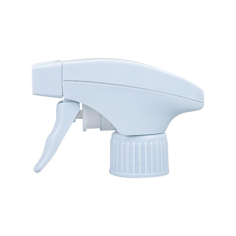
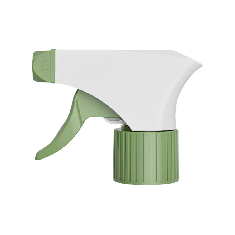 All Plastic Trigger Sprayer for Wholesale SupplyAll-plastic trigger sprayer with stable dispensing and leak-proof sealing, useful when the spring choice is still open and part-level material must be defined.View Product →
The all-plastic route is not automatically weaker, but it is less forgiving of vague specifications. Wall sections, ribbing, spring geometry, and friction surfaces need more thought up front. A sample that feels acceptable in the hand may still fail after a few hundred strokes if the drawing did not define return force and wear allowance.
Where Leakage Usually Shows Up on the Drawing
Leakage is rarely one failure. It is usually a chain of small allowances: a vent that is too small, a gasket land that is not flat, a check ball that does not seat, or a closure that feels tight but does not compress the seal evenly. The drawing should make each link visible.
- Vent path: air must enter the bottle as liquid leaves, without weeping at the closure.
- Check-ball seat: the seat angle and surface finish affect priming and backflow.
- Gasket compression: the drawing should show the sealing land, not just the gasket groove.
- Closure thread: thread form and bottle finish need to match across suppliers.
- Dip-tube fit: a loose tube can draw air; an over-tight tube can restrict flow.
- Shipping cap: the cap should protect the nozzle without forcing the trigger during transit.
Warning: A drawing that says “leakproof” without a test method is not a specification. Define the test orientation, duration, temperature, trigger cycles, and acceptable evidence before approval.
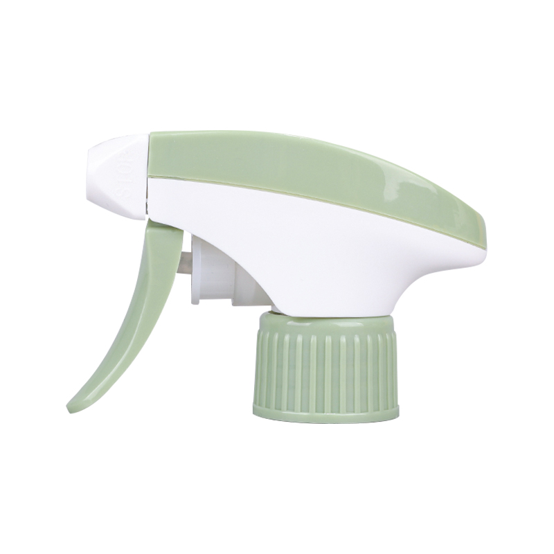
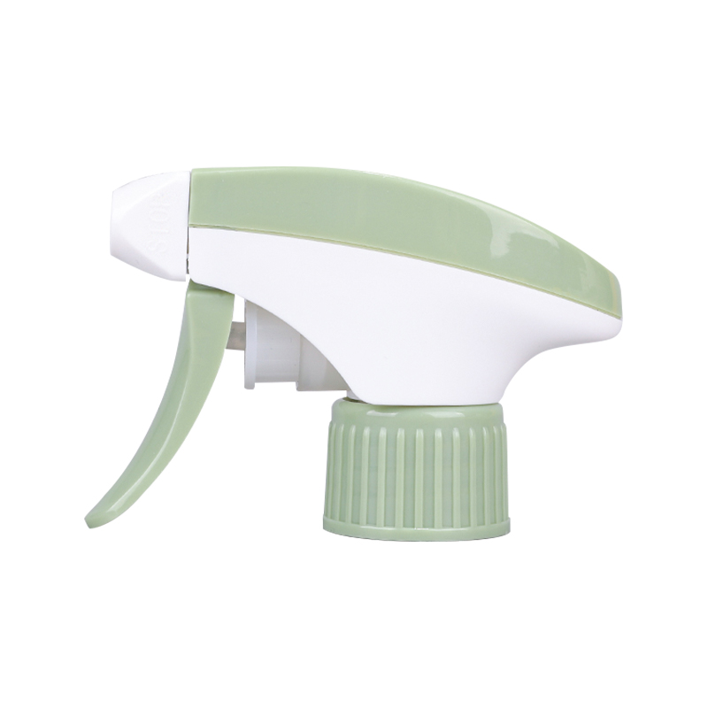 Leak-Proof Plastic Trigger Sprayer for Liquid DispensingPlastic trigger sprayer with corrosion resistance and a sealing structure to limit bottle-mouth or nozzle leakage; define test orientation and sealing dimensions before approval.View Product →
Leakproof designs still need a defined vent and a controlled closure seal. The drawing should show the intended sealing surface and identify which dimensions are checked on the first article, not only on a final functional sample.
Spray Performance Is a Specification, Not a Feeling
The spray pattern is the easiest thing to argue about because “too wide,” “too wet,” and “not fine enough” are opinions until they are measured. Put numbers and test conditions next to the expectation: output in milliliters per stroke with a tolerance, pattern diameter at a stated distance, droplet size range, spray angle, prime strokes, re-prime behavior, and trigger force.
For cleaning products, the pattern may need to cover a surface quickly without dripping. For personal care, the same pump family may need a softer, finer mist. For foam triggers, the drawing should define the foam quality, expansion, and nozzle insert, not only the liquid output. Trigger return time matters as well; a slow return feels cheap and can cause partial strokes in use.
Success: Write the test method beside the performance number. “Output: 1.2 mL per stroke” is weaker than “Output: 1.2 mL per stroke after five prime strokes, tested at 20°C with a stated fluid and a stated trigger speed.”
 Long Handle Foam Trigger SprayerFoam trigger sprayer using a special nozzle and internal pressure regulation to create stable foam; its long handle makes use context and leverage worth checking.View Product →
Long-handle foam triggers show why the drawing needs use context. The extra reach changes leverage, nozzle placement, and the way the user aims the product. A drawing that ignores the handle geometry can pass a bench test and still feel awkward in the hand.
How to Review a Trigger Sprayer Drawing Without a Toolroom Background
A five-minute red-flag review can save weeks. Look for missing materials, untoleranced critical features, and performance claims without a test method. Then check whether the drawing clearly separates the bottle interface from the sprayer internals.
Red flags to catch early
- No material or finish callout for the spring, gasket, or piston.
- Dip-tube length shown from the tube end rather than the sealing face.
- No vent path or no note about vent orientation.
- Spray output stated without fluid, temperature, or trigger speed.
- Assembly orientation left to the sample photo instead of the drawing.
- No revision block, approval date, or change history.
Info: A useful first article inspection should reference the drawing revision, not just the sample date. Otherwise a “passed” sample can become impossible to reproduce.
Ask for a section view at the seal and valve areas, and ask which dimensions are functional, cosmetic, or reference-only. A supplier who can answer those questions quickly usually has a clearer production process.
A Drawing Is Only Finished When the Sample Has a Verdict
The final test is not whether the sample sprays once. It is whether the drawing, the sample, and the inspection plan tell the same story. A controlled trigger sprayer drawing should give the buyer a clear verdict: dimensions that matter, materials that fit the fluid, a vent and seal strategy, performance numbers with test conditions, and a revision trail that survives the next production run.
That level of detail may feel slower at the quotation stage. In practice, it shortens the sample loop because the toolmaker, molder, and assembly team are working from the same assumptions. EAED’s experience across trigger sprayers, lotion pumps, foam pumps, and related dispensing packaging is built around that logic: define the interface and the function first, then protect them through tooling, injection, and assembly.
A good drawing does not guarantee a perfect sprayer. It does make the important problems visible before they become expensive, repeated, or difficult to explain.

 English
 русский
 Français
 Español
 italiano